Flashing
Flashing the AFC-Lite board
The AFC-Lite MCU can be connected with either CAN bus or USB.
If you choose to use CAN bus, follow this guide from Esoterical. This site also has a wealth of information on how to configure CAN bus if this is your first time using it.
If you choose to use USB, you will still need to run a 24 V+/V- cable to the AFC-Lite CAN bus port, just leave the CAN High/Low pins unpopulated. To flash the AFC-Lite for use with USB for data, follow this guide from Esoterial
Further details regarding the AFC-Lite can be found in the AFC-Lite manual.
After flashing and setting up connections/configurations appropriately, you should be able to either obtain the CAN bus
UUID (if using CAN) or the device serial path (e.g., /dev/serial/by-id/...) (if using USB) for the AFC-Lite MCU.
Please ensure you have these values before you proceed, as they will be required.
Make note of any toolhead sensor pins
If you are using FilamATrix, and are using toolhead endstop sensors, make a
note of what MCU pins those sensors are connected for the pre-extruder gear sensor (aka pin_tool_start) and
post-extruder gear sensor (pin_tool_end). Use these in the next step to properly install and configure AFC.
Note
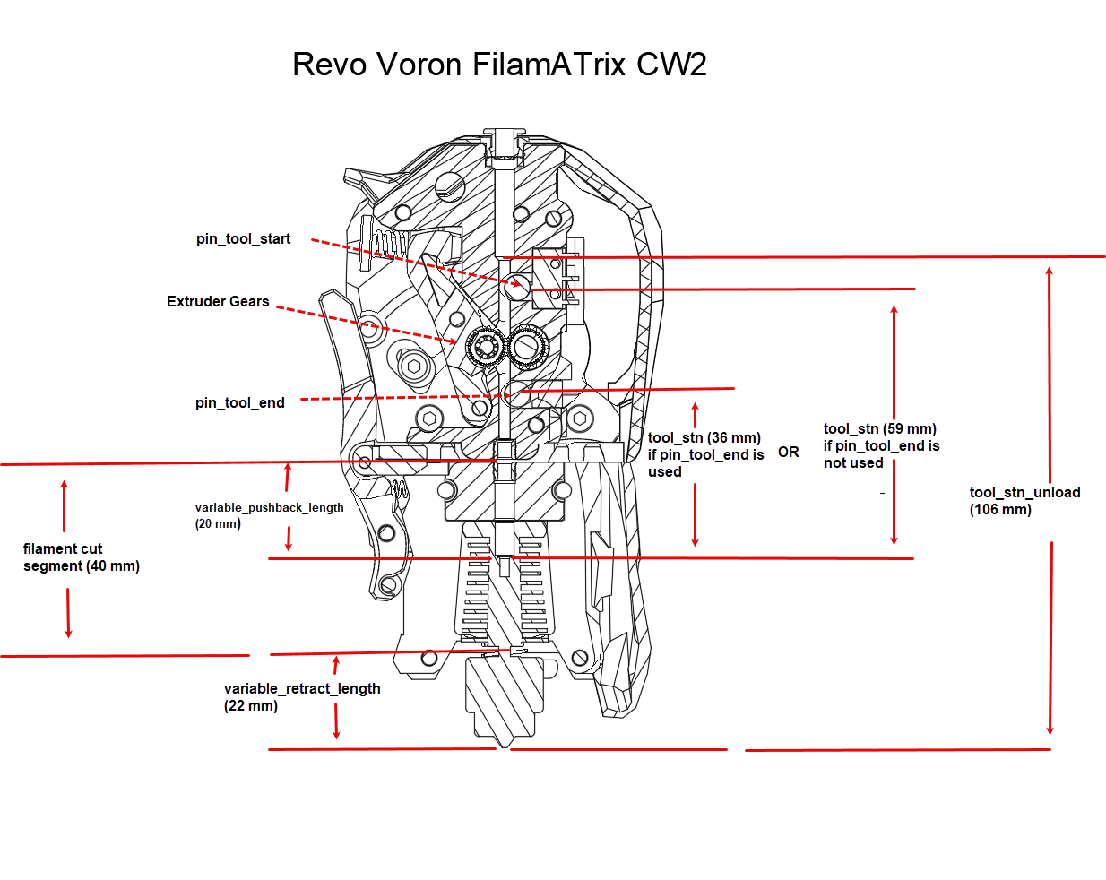
The pin_tool_start refers to the pin above the extruder gears, while the pin_tool_end refers to the pin below
the extruder gears. If you are using a single sensor, you will only need to use the pin_tool_start pin.
An example of these pins and their locations can be seen in the diagram below:
If you do not have a native toolhead filament sensor, you can use either an inline filament sensor such as Filatector, or you can use the TurtleNeck buffer as a virtual toolhead endstop, please see this guide for more details.